


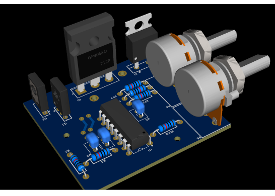

Variable Frequency and duty cycle driver
WARNING: This circuit can generate lethal voltages. Always use a fuse and keep your distance during operation. For educational use only.
Overview
This project is a high-performance Variable Frequency and Duty Cycle PWM Driver designed for power electronics applications like flyback transformer driving and DC-to-AC inverters. While the NE555 is a common choice for hobbyists, this design utilizes the TL494, a much more advanced and stable PWM controller that offers superior control over dead-time and frequency stability.
The Brain: TL494 PWM Generator
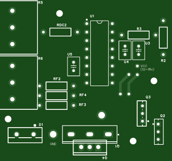
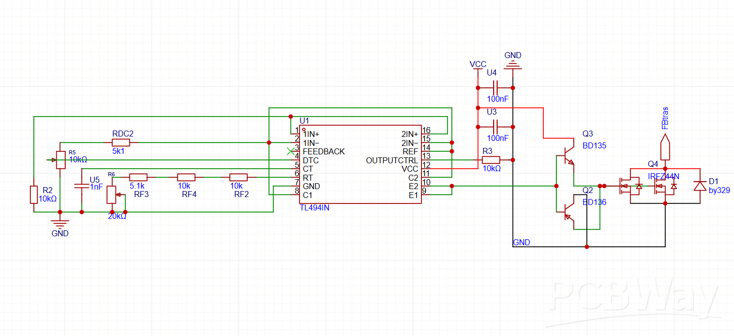
The TL494 is the heart of this circuit. It generates a precise PWM signal by comparing an internal sawtooth wave with a control signal. To set the operating frequency, the chip relies on an external Resistor (RT) and Capacitor (CT).
In this specific design:
RT (Timing Resistor): This is controlled by a combination of the potentiometer (R6) and the resistor network (RF2, RF3, and RF4).
CT (Timing Capacitor): This is the capacitor U5.
The frequency is calculated using the standard formula:
F=1.1/(RT x CT)
Key Features
-Dual-Parameter Control: Unlike simple drivers, this board allows you to adjust both the Frequency and the Duty Cycle independently using
on-board potentiometers.
-High-Current Power Stage: Featuring a dedicated Totem-Pole driver (BD135/136) to ensure the IRFP260N MOSFET switches cleanly and
stays cool even under heavy loads.
-Protection: Includes a footprint for a high-speed recovery diode (BY329) to protect the MOSFET from inductive spikes.
-DIY-Friendly Manufacturing: The project is designed as a Single-Layer PCB using only Through-Hole components, making it extremely easy
to etch and assemble at home.
-You can use an N channel Mosfet with package TO-247AC like IRFP260NPBF or TO-220 like IRFZ44N
Usage Instructions
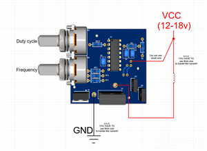
Power Supply: Connect a stable 12V-18V DC source to the VCC and GND pads.
Load Connection: Connect your transformer primary between the positive rail and the MOSFET Drain (refer to the wiring guide in the project images).
Tuning: Use the top potentiometer to sweep through the frequency range (in this case 24KHz to 44KHz) until you find the resonance point for your specific transformer. Use the bottom potentiometer to adjust the duty cycle for power control.
Applications:
-Flyback Transformer Driver
-Inverter driver to convert 12VDC to 220VAC
(be careful while working with HIGH VOLTAGE)
AND HAVE FUN
Variable Frequency and duty cycle driver
*Wpsload community is a sharing platform. We are not responsible for any design issues and parameter issues (board thickness, surface finish, etc.) you choose.


Attribution-NonCommercial-ShareAlike (CC BY-NC-SA) License
Read More⇒


Raspberry Pi 5 7 Inch Touch Screen IPS 1024x600 HD LCD HDMI-compatible Display for RPI 4B 3B+ OPI 5 AIDA64 PC Secondary Screen(Without Speaker)
BUY NOW


- Comments(0)
- Likes(2)
 More by Fady Jack
-
-
ARPS-2 – Arduino-Compatible Robot Project Shield for Arduino UNO
1909 0 5 -
A Compact Charging Breakout Board For Waveshare ESP32-C3
2510 3 7 -
AI-driven LoRa & LLM-enabled Kiosk & Food Delivery System
2597 2 0 -
-
-
-
ESP32-C3 BLE Keyboard - Battery Powered with USB-C Charging
2694 0 2 -


